
Adding Aquahot Control to eRVin
Controlling your Aquahot with eRVin can be fairly easily accomplished with some minor wiring additions using unused channels on your Firefly G5/G6 panel. While some of the photos of the wiring may look complex, don’t let that throw you, this is actually a fairly simple project.
Note: This site is a work in progress, links highlighted like this are place markers for posts that have not been written yet. Please check back later.
Concept:
 The basic concept involves paralleling a small relay with each of the Aquahot switches and turning the relay on/off with eRVin by attaching it to an unused Firefly channel. In use, the physical Aquahot switches will be left in the off position and eRVin will “override” or “bypass” them when the relay is activated. In my case I have only Burner and Electric Aquahot switches and used two of the unused Firefly channels. If your Aquahot also has the preheat switch the same technique can be applied.
The LED in the switch that indicates when the Burner or Electric are ON will behave accurately and reflect the true status.
Note: When the switches are set to off within the eRVin app, the physical switches on the Aquahot panel will remain fully functional and can be used normally to control the Aquahot. However, when the switches are set to on within the eRVin app, the physical switch will have no effect. Likewise, if the physical switches are set to on, eRVin will have no effect.
Design:
Below is a diagram of the circuit. It’s very basic, the Firefly channel (blue wiring) turns the relay coil on or off. The relay contacts simply connect across the Aquahot switch (red wiring) which is a simple single pole (SPST) switch. The black lines are the existing Aquahot wiring.

You may be wondering why I didn’t just let the relay on the Firefly G5/G6 channel output control the Aquahot switches. The reason is the Firefly channel output is referenced to the Firefly ground which is equal to chassis ground, but the Aquahot switches are connected to the Aquahot controller board and have additional circuitry between them and the chassis ground. I felt it was best not to potentially disrupt the controller logic, so by simply wiring across the switch contacts via a separate relay, the two systems remain completely isolated.
Parts:
 Small relays. The relay I used is an ELK-912. These are small and reliable, have screw terminals, high current contacts and only draw 30mA when active. In addition they have a built in snubber diode across the coil (which will protect the attached equipment from a high voltage “back EMF” spike that occurs when the coil is de-energized). I already had a few of these on hand, but there are probably other similar products available that will work just fine. However, I do not recommend using ordinary automotive relays, these are way overkill for this project, are larger and require significantly higher coil current (about 200mA). Plus most do not come with a snubber diode.
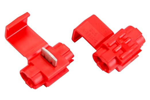
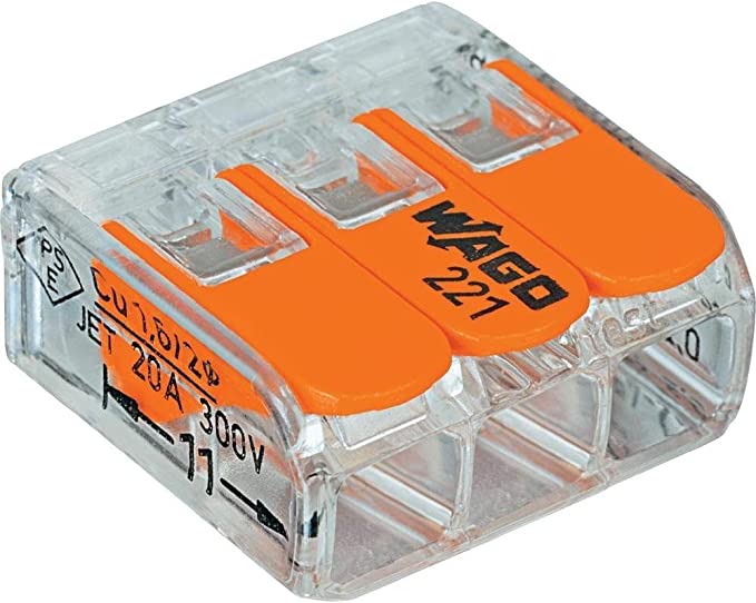
- Insulation displacement taps, male and female insulated quick disconnects or Wago lever connectors. If you use a tap, the new hookup wire will need to be within the same size range as the wire you are tapping. If you go this route I would suggest the red 18-22 gauge taps for this project. If you use quick disconnects or Wago connectors, you will be cutting the factory wires and crimping them on which I feel is a more secure connection and it is easier to mix wires of various gauges. The Wago connector shown accepts wire gauges from 24 thru 12 AWG.
- Several feet of stranded hookup wire. Anything 20 to 14 gauge should be fine. I used 14 but only because I had a lot of it left over from another project. If you will be using insulation displacement taps,18 gauge wire may be the best choice as I believe that is the gauge of the Aquahot switch harness wires.
- AMP 350550-1 connector pins for the Firefly back panel connections. This makes it clean and easy to tap into the unused Firefly channels. The same pin is used on both the G5 and G6 panels. Just crimp or solder some wire to the pin and push it into the empty hole on the connector body (unplug the connector from the firefly module first). You can purchase a professional crimp tool for these pins (very expensive), go with a cheap one, or simply solder or make your crimps with a pair of pliers. If you go with the cheap tool be warned that on the first attempt it takes a couple of tries to get the crimps done correctly so be sure to buy plenty of extra pins. Note that these pins will accept wire gauges from 14-20.


Preparation:
Remove the screws from the Aquahot and Gx panels. I also removed the door and catch from the cabinet, which on my 44B coach makes it much easier to work on the G6 panel.
Ideally you will want to disconnect power from the Firefly panel before commencing with this project. That is most easily accomplished by using the “salesman switch” next to the stepwell by the front door, or on the driver console.
Wiring:
On my 2017 Aspire I decided to use dimmer channels 28 and 36. 28 for the Electric and 36 for the Burner. In fact, use of these channels for the Aquahot are already programmed into the currently available images. The reason I chose to use dimmer channels instead of relay channels is I wanted to save the relay channels for some future uses like the door and cargo locks (no additional relay should be needed). Plus I have not come up with any use so far for additional dimmer circuits. However you may use whatever free channels you prefer.
- Start by identifying the location of the unused channels you want to use. They are fairly easy to find as usually the connector will have no wire inserted for that channel. I have marked the channel numbers on the connector body in the photo below (click to enlarge) which is of the G6 panel on my Aspire. Note there are five narrow circuit board modules that span across the width of the panel. G5 panels will be different, but hopefully the descriptions of the modules below should help you figure out how to find the channels you want to use:
- The top board (bottom of photo) with the green and orange RV-C wires connecting to it is the RSI board. This board occupies the space for channels 1-12 (which are not functional on this panel).
- The next board is a dimmer module for channels 13-24 (note that channel 15 is unused in this row).
- The board behind that is also a dimmer module but for channels 25-36. In the photo you can see that I have already added blue wires to channel positions 28 and 36.
- Behind that board is the relay module for channels 37-48.
- I’m not sure of the function of the remaining board, but it occupies the space of channels 49-60 (which are not functional on this panel).
- Once you have identified the location of the empty channels you want to use, crimp a pin onto a length of wire long enough to reach your relays. I just let my relays hang down into the cavity below the G6. Unplug the white connector body from the module and just push the pin in from the top. Leave the connector body unplugged until you finish the rest of the wiring.
- The other end of this wire will go to the + or POS terminal of the relay coil. See photo below.
- The – (GND) terminal of the relay will go to the panel or chassis ground. See photo above. The ground on my G6 was in the lower right corner, see the photo in step 1. This completes the relay coil wiring (blue lines in wiring diagram)
- Now lets identify the wires to tap into on the Aquahot switches. In the photo below the two wires we want are at positions marked 2 and 4 on the switch socket body.
- The easiest method to tap those wires is to use an insulation displacement tap as shown in the Parts list. However, the hookup wire and the harness wire must both be compatible with the tap. I think if you use 18 guage hook wire you can use a red (18-22) tap. In my case I used 14 gauge wire and therfore could not use a displacement tap since the the harness wires were 18 gauge. So instead, as shown in the photo below, I cut each harness wire installing a red quick disconnect on the switch end, then combining my relay wire with the other end of the cut wire. Combining my 14 gauge relay wire with the 18 gauge harness wire required a yellow 10-12 gauge quick disconnect.
- So whichever method you choose to tap the switch wires, one of the new wires from switch positions 2 and 4 will go to the COM connection on the relay, the other new wire will go to the NO (Normally Open) connection on the relay. This completes the relay contact wiring, the red lines in the wiring diagram.
- Double check all your wiring then go ahead and plug the white connectors back in place on the back of the Firefly panel.
- Power up the system and test for normal operation of the physical switches. When you have verified everything is working as expected power down again, carefully tuck the wiring back into the cavity and replace the panels.


Operation:
If you used channels 28 and 36 you can now open up the eRVin app, go to the Aquahot tab and remotely control your Aquahot! Be sure to leave the physical switches in the off position. Now when you turn on one of the functions from eRVin, you should hear the relay click faintly and the light on the Aquahot switch will go on.
Note: If you didn’t use channels 28 and 36 you will need to make some minor changes to Node-Red. See the post about Accessing Node-Red and/or contact me and I will try and talk you thru it, or remotely connect to your eRVin to make the changes.


Using with Alexa:
If you have Alexa, you can say “Alexa, turn on/off the Aquahot burner” or “Alexa, turn on/off the Aquahot electric”. You can also say “Alexa, turn on/off the Aquahot” and both switches will go on or off. See the short video clip below:
[…] Adding Aquahot Control to eRVin […]
[…] Adding Aquahot Control to eRVin […]